Research Topics
Skyrmions and chiral systems
Ferromagnets can be chiral due to the Dzyaloshinskii-Moriya interaction (DMI). In bulk materials, this interaction is caused by a lack of inversion symmetry in the crystal structure, but in thin films DMI can also be induced by symmetry breaking at interfaces. This chiral interaction favors rotation of the magnetization at short length scales, and, when strong enough, stabilizes chiral spin structures such as spin spirals, spin cycloids, and skyrmions.
In a collaboration with the Condensed Matter Theory group of the University of Antwerp, we theoretically study heterochiral ferromagnetic films, i.e., ferromagnetic films with a spatially modulated interfacially induced DMI. Chiral spin structures can be confined in regions with a strong DMI, which bears much potential for the design of potential applications. Besides examining the magnetic configurations, we also study the propagation of magnons in such magnetic heterostructures.
The figure shows the cycloidal ground state in absence of an external field and a skyrmionic ground state for an external field B in a high-DMI strip. In the shaded area outside the high-DMI strip there is no chiral interaction.
Exchange bias
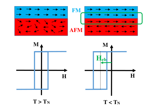
When cooling a ferromagnetic / antiferromagnetic bilayer in an external magnetic field below the Néel temperature, an unidirectional shift of the hysteresis loop (see figure) is observed due to the presence of frozen uncompensated antiferromagnetic spins at the interface. This shift is often accompanied by an enhanced coercivity and an athermal training effect, as the antiferromagnet is often in a metastable state after field cooling.
Using MuMax3, we can study the influence of this interface interaction on FM/AFM bilayers or investigate the stability of magnetic domain configurations in nanostructures. The exchange bias phenomenon is often used in GMR read heads, present in hard disk drives and can be used to enhance the thermal stability of magnetic nanoparticles.
The figure shows that the hysteresis loop of a ferromagnet is shifted antiparallel to the cooling field due to the interaction between the ferromagnetic and antiferromagnetic spins at the interface.
Artificial spin ice
The complex behaviour of magnetic systems is driven by the interplay of multiple interactions. In most magnetic systems, these interactions give rise to a single ground state. In some systems, however, the interactions are at odds with each other, leading to the inability of the system to minimize all its competing interactions: a property called frustration.
The oldest known example of a frustrated system is water ice, where each oxygen atom is adjacent to four others, placed in a tetrahedral configuration. The placement of the hydrogen atoms is determined by the ice rule that 2 are placed closer to the central oxygen atom, and 2 closer to one of its four nearest neighbours.
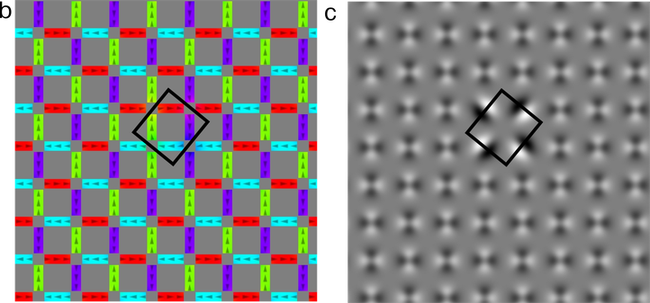
The ordering of the magnetic moments in a square lattice of magnetic islands (see figure below) is determined by a similar ice rule, called the 2-in, 2-out rule, which states that 2 magnetic moments should point towards and two out of each vertex. Because of their similarity to water ice, these systems are called spin ices.
Figure b depicts the magnetization state of the ground state background configuration with a local excitation on top of it, while (c) is a close-up of the simulated MFM image, generated with MuMax3.
Domain wall motion
In the absence of magnetocrystalline anisotropy, the magnetization in a magnetic nanostrip is typically aligned along the length axis of the strip due to the shape anisotopy. Whenever the magnetization at two ends of the nanostrip are aligned antiparallel, there will be a small region in between where the magnetization turns 180 degrees; these regions are called domain walls.
The figure below shows a transverse domain wall in a permalloy nanostrip with the magnetization direction indicated by the direction of the arrows and the color.
The fabrication process of nanostrips dictates that disorder is always present in the crystal structure of the nanostrips. Polycrystalline materials are crystalline materials without long-range order in the crystal lattice. Typically, when a thin film is grown, a few seeds are present around which the other atoms place themselves. In this way, a material grain grows until it finds a neighbouring grain. Grain properties as grain size, thickness, etc. can vary, and there is a mismatch between the crystal lattices at the grain boundaries. Because this has a influence on the magnetization dynamics of the nanostrip, we extended MuMax3 with the possibility to easily simulate polycrystalline materials.
As an example, the figure below shows a nanostrip divided into different material grains by a Voronoi tessellation. Each different gray shade represents a different material region.
In our group, we look at the mobility of a domain wall in a nanostrip under the (combined) influence of disorder, thermal fluctuations and driving forces like magnetic fields and spin polarized currents.
Simulations
MuMax3 software package
Former postdoc in our group Dr. Arne Vansteenkiste developed MuMax3
Since then it was extended several times within our group, e.g. with the possibility to simulate disordered materials, antiferromagnets, or chiral magnets.
Hardware
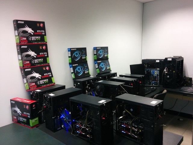
Next to the personal workstations, our group makes use of a 20 GPU cluster which is managed using mumax3-server.
Experimental methods
Magneto-optical FMR
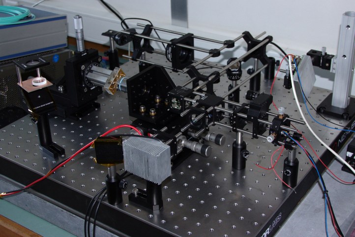
MOKE-FMR tries to combine to advantageous aspects of TRMOKE (high sensitivity and spatial resolution) with the ease of use of conventional strip line FMR. The technique has not been explored earlier and resulted in a new setup. In short, linearly polarized laser light illuminates the sample. Through the Magneto-Optical Kerr Effect , the polarization direction is modulated at picosecond level. An ultrafast photodiode in combination with an analyzer crystal then allows to investigate the dynamics. The new setup is named: Magneto-Optical Network Analyzer a.k.a. MONA . Our magneto-optical FMR setup is able to resolve magnetization dynamics up to 20GHz and 700nm.
Magnetic Force Microscopy
Magnetic Force Microscopy is a technique based on AFM. A magnetic tip is moved over the surface of a sample and the phase shift, which is proportional to the force gradient and so the second derivative of the stray field, is measured. Each line is scanned twice. First the topography ( using AFM ) is detected and in the retrace one makes use of a constant lift height in order to eliminate the van der Waals forces, etc. So in the retrace the tip is only deflected under influence of the magnetic force. Because MFM has is slow, this technique is used to investigate static magnetic configurations of a certain sample, e.g. magnetic vortices in a nanodisk or domain walls.
Time-resolved STXM
Scanning transmission X-ray microscopy (STXM link https://en.wikipedia.org/wiki/Scanning_transmission_X-ray_microscopy) can be combined with XMCD (X-Ray Magnetic Circular Dichroism for high resolution magnetic imaging. Together with the team at the Maxymus STXM at the BESSY II synchrotron in Berlin, Germany we are developing and using time-resolved STXM, using special in-house developed high speed data acquisition. They allow us to combine atime resolution of up to the picosecond level (several gigahertz) with high spatial resolution (~25nm) for the investigation of dynamics in nano magnets.


